- 01
Concept design
The supply concept, voltage levels, redundancy and space for substations and technical rooms are defined from the building brief and agreed with the client and the architect.
DeliverableDesign brief, preliminary single-line diagram, room schedule
- 02
Basic design and load calculations
Installed and demand loads, diversity, transformer and generator ratings and power-factor correction are calculated from the load schedule.
DeliverableLoad schedule, transformer and generator sizing note
- 03
Short-circuit and selectivity studies
Fault levels are calculated at every board to IEC 60909, and breaking capacities and discrimination between protective devices are verified to IEC 60947-2.
DeliverableFault-level report, selectivity tables, protection settings
- 04
Cables, earthing and lightning protection
Cross-sections follow current-carrying capacity, grouping and voltage drop (IEC 60364-5-52). Earthing and bonding follow IEC 60364-5-54 and lightning protection follows an IEC 62305 risk assessment.
DeliverableCable schedule, earthing layout, lightning-risk assessment
- 05
Detailed design
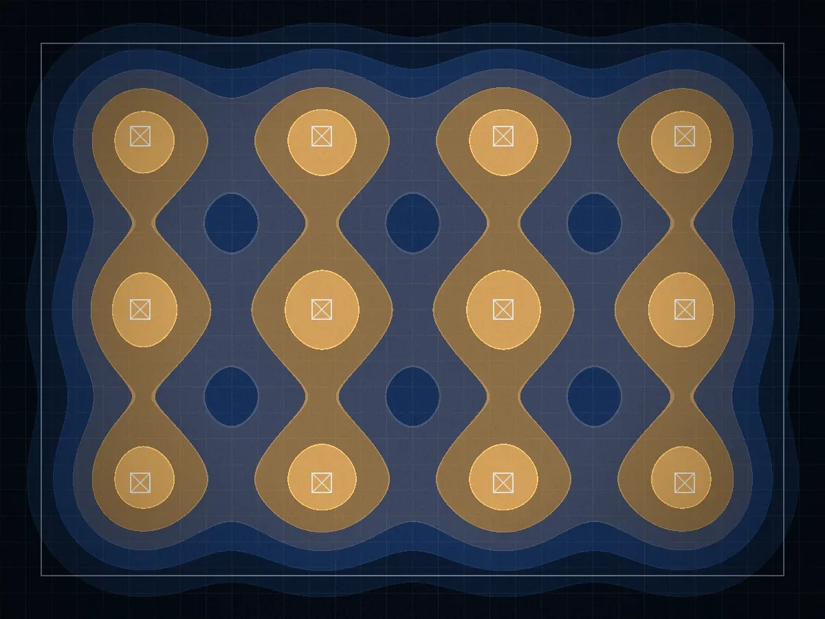
Single-line and schematic diagrams, layouts and cable routes are drawn, and lighting is calculated in DIALux, with levels taken from EN 12464-1.
DeliverableSingle-line diagrams, layouts, schematics, lighting calculation
- 06
Specifications, BOQ and as-built documents
Technical specifications and a priced bill of quantities are issued for approval and tender. After construction, as-built documents record the installation as built.
DeliverableSpecifications, bill of quantities, as-built drawings